Rigid-framed electric locomotive

Rigid-framed electric locomotives were some of the first generations of electric locomotive design. When these began the traction motors of these early locomotives, particularly with AC motors, were too large and heavy to be mounted directly to the axles and so were carried on the frame. One of the initial simplest wheel arrangements for a mainline electric locomotive, from around 1900, was the 1′C1′ arrangement, in UIC classification.
Some of these locomotives had their driving wheels coupled with coupling rods, as for steam locomotives. Others had individual motors for each axle, as would later become universal.
By the middle of the century, the bogie arrangement for locomotives became more popular and rigid-framed locomotives are now rare, except for small shunters.
1′C1′
[edit]
1′C1′ is the UIC classification for a railway locomotive with a wheel arrangement of three coupled driving wheels, with a leading and trailing articulated pony truck. The driving wheels are coupled by external coupling rods.
The description is most commonly applied to some locomotives from the early decades of electric locomotive design, when the traction motor or motors were mounted on a rigid frame and drove all the driving wheels coupled together. To permit higher speeds for fast passenger services, leading pony trucks were added. An advantage of electric locomotives was that they could easily have two driver's cabs, so avoiding the need to turn them at terminus stations and so the wheel arrangement was made symmetrical to run equally well in both directions.
Steam locomotives
[edit]
The equivalent is 2-6-2[i] or 2-6-2T Prairie arrangement for steam locomotives was a popular one for a long period. The first was the South African Cape Government Railways 2nd Class 2-6-2TT of 1875. Building of 2-6-2T classes, such as the GWR Prairies or Standard Class 2s, continued almost to the end of steam.
Many of these prairies were tank engines, which were able to run equally well in either direction. This was aided by the symmetry of the wheel arrangement. These were often used for suburban passenger services, which needed fast turnarounds at city terminus stations, without needing to turn the locomotive on a turntable. Although quite powerful locomotives were used, to give good acceleration between closely spaced stations, they did not need the sustained speed or fuel capacity of an express locomotive.
Electric locomotives
[edit]Italy
[edit]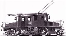
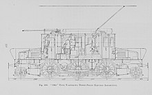
This first 1′C1′ arrangement was only a common one for electric locomotives in the early years. It was used for some early AC examples, mostly Italian, between 1900 and 1920. Italian railways had begun electrification with a low-frequency three-phase AC system, to the designs of the Hungarian Kálmán Kandó. These used large, 2 metre diameter, motors, powerful enough that only one or two motors were needed for the locomotive, but also too large diameter to be mounted easily for a drive to the axle. Accordingly, Kandó frame mounted the motors on resilient springs and used coupling rod drives to the wheels.[1]
The first of these locomotives were the Italian RA 361, later FS class E.360, for the 1902 electrification of the Valtellina line.[2]
For these early small locomotives, the power was sufficiently low that both motors could be coupled to the crankpin of the centre axle with a simple rigid triangular coupling rod. Secondary rods carried the drive to the other wheels. The motors were rigidly mounted to the frames and so the centre crankpin had a vertical slide mechanism in the triangular rod, for suspension travel.[1] Each of these two motors were rated at 600 bhp and weighed 8.2 metric tons, 40% of the total weight of the locomotive.[3]
France
[edit]

The 1′C1′ arrangement was considered as something of a standard pattern for small passenger locomotives, so that when the French Chemins de fer du Midi electrified at 12 kV 16⅔ Hz AC in 1912, six locomotives of this type were ordered for trials, from the major electric locomotive makers of Europe: E 3001, E 3101, E 3201, E 3301, E 3401, E 3501. Only E 3201, built by the American Westinghouse, was considered successful and it lasted in service under the SNCF as 1C1 3900 until 1959. E 3401, by Jeumont, used the 1′Co1′ layout, with separate motors for each axle.[4]
When the production locomotives from these prototypes were to be built, they were to follow the Westinghouse design of E 3201 but they were so delayed by the war that when they emerged as 2C2 3100 they had become a 2′C2′ design with bogies instead of pony trucks and with three vertically mounted motors by Dick, Kerr of Britain, not Westinghouse.[4]
Sweden
[edit]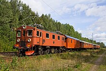
Some of the last 1′C1′ locomotives in service were the Swedish SJ D and Da classes. The D class were built from 1925 to 1943 in several sub-variants and a modernised version, the Da, in the mid 1950s. Both remained in service until around 1990. Both had a pair of traction motors, up to 1,840 kilowatts (2,470 hp) for the Da, and retained the coupling rod drive. The motors were geared to a single jackshaft placed level with the other axles, in the position where a third equi-spaced axle would have been, and so did not require the complicated or heavy triangular drives of earlier designs.[5]
Diesel locomotives
[edit]1′C1′ was not generally used for diesel locomotives. The overlap between viable diesel locomotives, owing to the development of the first high-speed diesel engines from around 1930, and the era of small rigid framed driving wheels was short. The first diesel shunting locomotives were of C or 0-6-0 wheel arrangement,[ii] as they were neither heavy enough nor fast enough to need the pony trucks. These low-powered shunting locomotives could also make do with a single traction motor.
More powerful mainline locomotives used multiple traction motors, one per axle. This was mostly due to the locomotive's generator being able to produce DC current, thus allowing simpler and more controllable DC motors to be used. These could easily be made in the smaller diameters needed for per-axle use, rather than the large diameter many-pole AC motors. As diesel locomotives developed, the per-axle traction motor design became ubiquitous, with 1′Co1′ and 1′Do1′ designs in early years, later with bogies as Bo′Bo′, then Co′Co′ and heavier designs.
A rare exception was the Armstrong Whitworth hydrostatic drive locomotive of 1929 for the Buenos Aires Great Southern Railway of Argentina. This used a single transmission and jackshaft drive from one end, with coupling rods. The locomotive was unsuccessful, owing to problems with the transmission and lay unused for several years before being scrapped in 1943.[7][8]
![]() Media related to 1′C1′ locomotives at Wikimedia Commons
Media related to 1′C1′ locomotives at Wikimedia Commons
1′Co1′
[edit]The 1′Co1′ wheel arrangement was similar, except that the wheels were driven by separate traction motors for each axle, rather than them being coupled together. As each axle was driven, there was no longer a need for the coupling rod connection between them. This independence would in time raise the issue of wheelslip, starting with a single axle, but that was not an issue for the early locomotives, with their low ratios of power to adhesive weight.
Diesel-electric locomotives used the 1′Co1′ arrangement with separate traction motors, rather than the coupled 1′C1′. This was because these were some decades later than the first electrics, by which time traction motor technology had developed. Also the generators on board the locomotive could generate DC, rather than AC. Control of DC was more sophisticated by this time and there was no need for the traction motors to be the large diameter that the 1900 AC electrics had required.[9]
The first British mainline diesel locomotive, Armstrong Whitworth's 800 bhp locomotive built for the LNER in 1933, was of this type.[10][11] This locomotive was unsuccessful and scrapped after only a few years, in 1937.
![]() Media related to 1′Co1′ locomotives at Wikimedia Commons
Media related to 1′Co1′ locomotives at Wikimedia Commons
2′C2′
[edit]
In 1914 Italian State Railways constructed two series, the E.331 and E.332, of three-phase AC locomotives. These were intended to be a development of the 1′C1′ E.330, suitable for lighter secondary lines. The heavy central V coupling rod and closely set paired motors of the E.330 were replaced by two motors set either side of the transformer and control gear, and with a lighter rod drive in order to reduce Hammer blow, using lighter rods and a pair of jackshafts set beyond the coupled wheels. Placing the jackshafts at axle level reduced the articulation angles needed in the coupling rods, so avoiding the mass of the older triangular rods, or the need for vertically-slotted crank bearings. Overall, this reduction in reciprocating mass had the effect of making the overall locomotive heavier and with greater overhang at the ends, requiring bogies rather than pony trucks.
![]() Media related to 2′C2′ locomotives at Wikimedia Commons
Media related to 2′C2′ locomotives at Wikimedia Commons
2′Co2′
[edit]
After the initial promise of 1,500 V DC electrification on the Shildon–Newport line coal traffic, the North Eastern Railway commissioned a large express passenger locomotive, later classed as EE1. Although the mainline electrification through York never took place, the locomotive itself was a success in its brief trials. The 6 ft 8 in (2.032 m) driving wheels were unusually large, following the steam locomotive practice with which Darlington Works were more familiar, and the electrical equipment was supplied by Metropolitan-Vickers of Manchester. The locomotive was heavy for a DC electric and in consideration of its high design speed, four-wheel bogies were used at each end.
![]() Media related to 2′Co2′ locomotives at Wikimedia Commons
Media related to 2′Co2′ locomotives at Wikimedia Commons
(1′Co1′)+(1′Co1′)
[edit]
The American New Haven EP-2 of 1919–1927 combined two 1′Co1′ sub-frames beneath a single boxcab body to make a (1′Co1′)+(1′Co1′) locomotive.[12] As the two frames were articulated together and the body on top was not a structural component, this was a (1′Co1′)+(1′Co1′) rather than (1′Co1′)(1′Co1′); i.e. articulated in two units, rather than with bogies beneath a single structure. At 2,000 hp, they were around the same power as a pair of the previous EP-1s, which had often worked in multiple, although also lighter and more stable at speed.[13]
The EP-1s had required conversion from a Bo'Bo' arrangement to (1′Bo)(Bo1′), in order to prevent oscillation or 'nosing' when running at speed.[13] The same use of pony trucks was designed into the EP-2 from the outset. The central carrying axles were largely pointless though, having no guiding function. When additional locomotives, the EP-3 and then EP-4, were required in the 1930s, these used a (2′C)+(C2′) arrangement, with the carrying axles moved to the ends as twin-axle bogies.[12]
1′B1′
[edit]
The smaller four-driver 1′B1′ layout was not generally used, but the Swiss narrow-gauge Rhaetian Railway did have one class of seven, the Ge 2/4 in 1912. These were low-frequency AC locomotives with a single repulsion motor mounted in the body, driving by rods downwards to a central jackshaft and then to the driving wheels.
1′D1′ and 1′E1′
[edit]
Larger and heavier locomotives required more driving wheels, in order to provide enough adhesion whilst limiting axle load. Some earlier locomotives had already had four driven axles, but these had used either the B+B articulated arrangement or Bo′Bo′ with separate traction motors for each axle and two bogies.[iii]

The first electric locos to extend the 1′C1′ arrangement to 1′D1′ were the Swiss 440 kilowatts (590 hp) Rhaetian Railway Ge 4/6 class of 1912.[iv] In the same year, the Bern–Lötschberg–Simplon railway's BLS Fb 5/7 used a 1′E1′ arrangement, with five driven axles, two traction motors of 1,250 horsepower (930 kW) each and a rigid triangle rod drive to the centre axle. At the time, these were the world's most powerful electric locomotives.[15] Each motor weighed 14 tons and was supplied by a separate transformer with a 12-stage tap changer. The taps for each motor were changed alternately, giving an effective 24 step control. The Swiss railways used low-frequency single-phase AC, at 11 kV for the Rhaetian and 15 kV for the BLS.
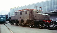
By 1922, the Italian three-phase system was also using heavier and more powerful 1′D1′ locomotives, such as the FS class E.431. These now had a wheelbase so long that a Zara bogie was used to articulate them.
![]() Media related to 1′D1′ locomotives at Wikimedia Commons
Media related to 1′D1′ locomotives at Wikimedia Commons
1′Do1′
[edit]
Electric railways in the US had begun with low-voltage DC systems: 675 V (Baltimore) and 660 V (New York). These early systems were based on direct connection to DC traction motors, without needing rectification, transformers or large diameter motors. Adequate power for main line haulage, even for the slower services through tunnels to the major urban terminuses, required multiple motors. The Baltimore and Ohio used articulated Bo+Bo steeplecabs from the outset in 1895, the first main-line electric locomotives and over nine times heavier and more powerful than anything electric before.[14] The New York Central S-Motor though was a single rigid frame with four separately driven axles and two leading and trailing trucks.[16] The traction motors at this time were simple ungeared motors, with the rotor mounted around the axle shaft.[17] Two-pole bipolar motors were used, where the rotors were sprung with the axles and wheels and the field coils fixed. As there were only two poles, horizontally to the sides of the rotor, the rotor was free to move up and down between them with the suspension.

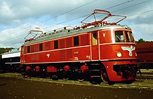
The multiple motor Do arrangement, compared to the rod-drive locomotives and despite their powerful AC motors, had advantages for running at high speed, with no reciprocating mass to balance or give hammer blow. Once geared and isolated traction motor drives were available, their unsprung weight could also be reduced, encouraging smooth running. Although many locomotives adopted the Bo′Bo′ bogie arrangement and abandoned rigid frames, some fast passenger locomotives retained them into the 1940s and remained in service into the 1990s. Their large diameter driving wheels encouraged smooth running at speed and reduced the speed required from the motors and their gearing. Retaining frame-mounted motors also allowed large motors and adequate space for cooling airflow. A further advantage for four-motored Do locomotives, rather than the three-motored Co arrangement, is the ease with which the four motors can be switched between series, parallel and series-parallel circuits. When this was used for three-motored locomotives, a double-wound armature on the motor was required.
Germany constructed a series of these pre-war, the DRG class E 16, E 17, E 18 (Austrian ÖBB 1018) and E 19. They were of increasing technical sophistication, the first having the Buchli drive, later cup drives.
The power required for the last of these, the E 19, was such that double traction motors were required with two motors for each axle.
![]() Media related to 1′Do1′ locomotives at Wikimedia Commons
Media related to 1′Do1′ locomotives at Wikimedia Commons
(1′Do1′)+(1′Do1′)
[edit]
The Great Northern Z-1 class locomotives of 1927 were of 1′Do1′ layout, but operated as permanently coupled pairs, effectively (1′Do1′)+(1′Do1′). Each was built with a driving cab at each end, although only one was equipped. This gave them the possibility to be used as separate 1′Do1′ locomotives at some future time,[18] although this was never needed in practice and they remained coupled until withdrawn in favour of dieselisation in the mid-1950s.
(1A)Bo(A1) and the 'Java bogie'
[edit]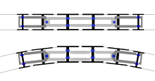

This little-known variant of the 1′Do1′ articulates the trucks at each end by forming a bogie with one driven axle and one carrying axle.
Only a few examples of the (1A)Bo(A1) were built. They originated in Switzerland with the work of Jakob Buchli of BBC, later Swiss Locomotive and Machine Works. The first were four ESS 3000 express passenger locomotives, built by SLM and BBC in 1924 in Switzerland for the Electrische Staats Spoorwegen of Java. These gave their name to the 'Java bogie' for this form of articulation.
The bogie was arranged so that the pivot axis was just behind the pivoted driven axle. The axles were driven by Buchli drives, to permit suspension movement, and as the pivot was so close to the axle this linkage could also absorb the bogie's movement, as the driven axle twisted in place but did not move sideways by much.
They were followed in 1926 by the two JGR class 7000, later classified as ED54, for Japan, also built by SLM / BBC and with Buchli drives. These performed well, compared to other Japanese locomotives with nose-suspended traction motors, but were thought complicated and non-standard. With the culture of 1930s Japan and the increasing demand for self-reliance, rather than importing locomotives from overseas, they were used little and were withdrawn in 1948, despite this being the height of Japanese rebuilding post-war.[19]

A group of three different trial express passenger locomotives were supplied for the 1,500 V DC Great Indian Peninsula Railway in 1928. The first of these was most successful and followed by the GIPR EA/1 class of 21 and later the single GIPR EA/2. They were asymmetric, with a 2′Bo(A1) arrangement and a Java bogie at one end; a four-wheeled bogie at the other supported the electrical equipment. This electrical equipment was supplied by Metrovick but the locomotives were built by SLM and used their Winterthur drive, with paired traction motors above each axle, driving through a single central gear. The high-mounted motors were also found useful for services on flooded lines during the Indian monsoon.

A derivative design was used for the Swiss 'double locomotives' of 1931, built for heavy freight service on the steep gradients of the Gotthard Railway. These consisted of two articulated units as (1A)A1A(A1)+(1A)A1A(A1). A further unpowered carrying axle was also provided, splitting the central Bo group into A1A, which was needed by the extra weight of the transformer for the Swiss low frequency AC system. Again this was only a small class of three locomotives classed as SBB Ae 8/14, although each of the three was different. The first used the same Buchli drives, but from the second they introduced the Winterthur Universal Drive, with paired traction motors driving each axle through a single central gear. This could be adapted more easily to the articulation. A drawback to the sheer size of these locomotives is that there were few trains heavy enough to require them, and when used to the full they were at risk of over-straining their couplings

The Swiss SBB Ae 4/6 of 1941 was derived from half of the 'double locomotive', with a more modern flat-fronted cab at each end. Weight saving in the traction motors allowed a return to the (1A)Bo(A1) layout, with the Java bogie and the Winterthur drive and avoiding the central carrying axle. They were also intended for use on the Gotthard route, but more flexibly as they could be used as individual units for lighter trains, or run in multiple as pairs for heavier trains. Both these and the Ae 8/14 had used regenerative braking, useful for descending the Gotthard's steep gradients without overheating and also returning electrical power to the network. The Ae 4/6 had a simplified and lighter system, where one traction motor could serve as the exciter for the others during braking. They were also built with aluminium windings in the transformer and motors, rather than copper.
In service, the Ae 4/6 performed well in some aspects, but had problems with a lack of adhesion and mechanical unreliability. Some aspects of their wartime construction may have reduced their mechanical build quality, leading to high noise levels in the final drives, and a susceptibility to bearing and gear failures, particularly after wheelslip.

A Dutch class, the NS 1000, were ordered from the same makers but were delayed by the war until 1948. Three were built by SLM, but the remainder were licence-built by Werkspoor in the Netherlands. Although designed as passenger locomotives with a top speed of 160 kilometres per hour (99 mph), they were soon found to be unreliable when used at speed and spent their working lives restricted to 100 kilometres per hour (62 mph) and mostly freight services. Despite this, they stayed in service until 1982.
![]() Media related to (1A)Bo(A1) electric locomotives at Wikimedia Commons
Media related to (1A)Bo(A1) electric locomotives at Wikimedia Commons
2′Do2′
[edit]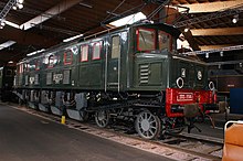
The ultimate development of the rigid-framed electric locomotive was the 2′Do2′ arrangement. Four wheeled bogies replaced the pony trucks, giving better stability at high speeds. Four separate traction motors allowed high power. Sometimes a double traction motor was used, where two motors were geared to the same axle.
The arrangement was first used as a conversion of the first production 1′Do1′ New York Central S-Motors, then known as the T-2, after an accident two days after entering service in 1907. They were then rebuilt as 2′Do2′ with bogies rather than single axle trucks and renamed to their original name as 'S-Motors'.[16]
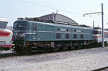
This arrangement was used in France, with the pre-war 2D2 5500 (1929–1943) and related classes, then the much improved post-war 2D2 9100 (1950).[20]
In the mid-1950s, the WAGR X class diesel-electrics were built for the 3 ft 6 in Western Australian railways. Their additional carrying axles allowed a low 12 ton axle loading, permitting their use across the whole network.
![]() Media related to 2′Do2′ locomotives at Wikimedia Commons
Media related to 2′Do2′ locomotives at Wikimedia Commons
2′Do1′
[edit]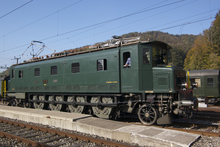
The Swiss also used a large four-axle similar to the 2D2 5500, the 2′Do1′ Ae 4/7 (1927–1934).[21] If length of service is considered, these were one of the most successful electric locomotive classes, lasting seventy years in service. They were a development of an earlier three-axle 2′Co1′ class, the Ae 3/6 I. Both of these had an asymmetrical layout, with the pony truck at one end replaced by a four-wheel bogie. The Swiss low frequency AC system had the drawback of requiring heavy main transformers, compared to a 50 Hz system, and these were mounted at one end of the loco, needing the extra axle to carry their weight.[21]
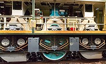
All of these, both French and Swiss, used Buchli drives to couple the traction motors to the driving axles. The original Swiss drive used a single Buchli gear on one side to drive each axle, the French locomotives used a double-sided drive with the Buchli gear duplicated for each end of the axle, which was considered to reduce wear.[v][20]
![]() Media related to 2′Do1′ locomotives at Wikimedia Commons
Media related to 2′Do1′ locomotives at Wikimedia Commons
2′D1′
[edit]Asymmetrical layout had also been used for the Prussian EP 235 for the Silesian Mountain Railway in 1918. This was the first of a number of 2′D1′ classes, also to support the weight of a large offset low-frequency transformer.[22] They remained in service until the 1950s. These 2′D1′ classes began as a reluctant single prototype, built for comparison with the articulated 2′B+B1′ Prussian EP 209, which had themselves been a reaction to the poor performance of the 1912 1′D1′ Prussian EG 501.
![]() Media related to 2′D1′ locomotives at Wikimedia Commons
Media related to 2′D1′ locomotives at Wikimedia Commons
A rare example of the 2′D2′ layout was the unique British diesel-mechanical Fell locomotive of 1955.
References
[edit]- ^ In the Whyte notation for wheel arrangements, as widely used for steam locomotives in the English-speaking world.
- ^ Such as the Armstrong Whitworth 40-ton shunters.[6]
- ^ Such as the first Baltimore and Ohio Bo+Bo locomotives of 1895 for the Howard Street Tunnel.[14]
- ^ See Swiss locomotive and railcar classification for an explanation of the 4/6 and 5/7 notation
- ^ The belief was not merely that the two gears shared the load, thus the rate of wear, but also that it reduced the effects of torsion in the shaft. A similar effect was noted with the phasing gears of the early Napier Deltic engine.
- ^ a b Parshall & Hobart (1907), p. 332.
- ^ Parshall & Hobart (1907), pp. 330–341.
- ^ Parshall & Hobart (1907), p. 332–335.
- ^ a b Ransome-Wallis (1959), pp. 149–150.
- ^ Modern Locomotives (2000), pp. 52–53, Class D.
- ^ Webb (2010), pp. 44–49.
- ^ Webb (2010), pp. 8, 15–16.
- ^ "Armstrong Whitworth Worldwide Locomotive & Railcar Production". Derby Sulzers.
- ^ Allen, Today and Tomorrow, pp. 49–51.
- ^ "Armstrong Whitworth Locomotives & Railcars in the United Kingdom". Derby Sulzers.
- ^ Webb (2010), pp. 93–113.
- ^ a b Solomon (2003), p. 37.
- ^ a b Solomon (2003), pp. 32–36.
- ^ a b Modern Locomotives (2000), pp. 26–27, Nº 1–3 Bo+Bo.
- ^ Modern Locomotives (2000), pp. 34–35, Be 5/7 1-E-1.
- ^ a b Modern Locomotives (2000), pp. 30–31, Class S 1-Do-1.
- ^ Solomon (2003), pp. 16–19.
- ^ C.E. Baston, Westinghouse (February 1927). "Motor Generator Locomotives for the Great Northern Railway". Railway and Locomotive Engineering. XL (2): 52–54.
- ^ Haut (1970), p. 90.
- ^ a b Modern Locomotives (2000), pp. 98–99, Class 9100 2-Do-2.
- ^ a b Modern Locomotives (2000), pp. 56–57, Class Ae 4/7 2-Do-1.
- ^ Ransome-Wallis (1959), pp. 150, 153.
- Sources
- Allen, G. Freeman (1962) [1959]. British Railways today and tomorrow (3rd ed.). Ian Allan.
- Haut, FJG (1970). The Pictorial History of Electric Locomotives. Oak Tree Publications. ISBN 0-498-07644-X.
- Hollingsworth, Brian; Cook, Arthur (2000). Modern Locomotives. ISBN 0-86288-351-2.
- Parshall, H. F.; Hobart, H. M. (1907). Electric Railway Engineering. London: Archibald Constable. OL 23297005M.
- Ransome-Wallis, P., ed. (2001) [1959]. Encyclopedia of World Railway Locomotives. Dover Transportation. Courier Corporation. pp. 149–150. ISBN 0486412474.
- Solomon, Brian (2003). Electric Locomotives. Voyageur Press. p. 37. ISBN 1610606264.
- Webb, Brian (2010). Armstrong Whitworth: A Pioneer of World Diesel Traction. Lightmoor Publishing. ISBN 9781899889457.
